Getting your transformer specs wrong is expensive. Wrong voltage configuration, inadequate cooling, or missing accessories mean rework, delays, and equipment that doesn't integrate with your system all add up to a massive headache. A poorly specified transformer means project delays, damaged equipment, and unexpected costs.
But how can you spec the right distribution transformer for your build?
In order to specify an electrical transformer, you need to understand your load requirements, operating environment, and some key technical details related to your application. This post will walk you through how to spec with confidence, starting with the fundamentals and working through the nitty-gritty details.
.avif)
What is a distribution transformer?
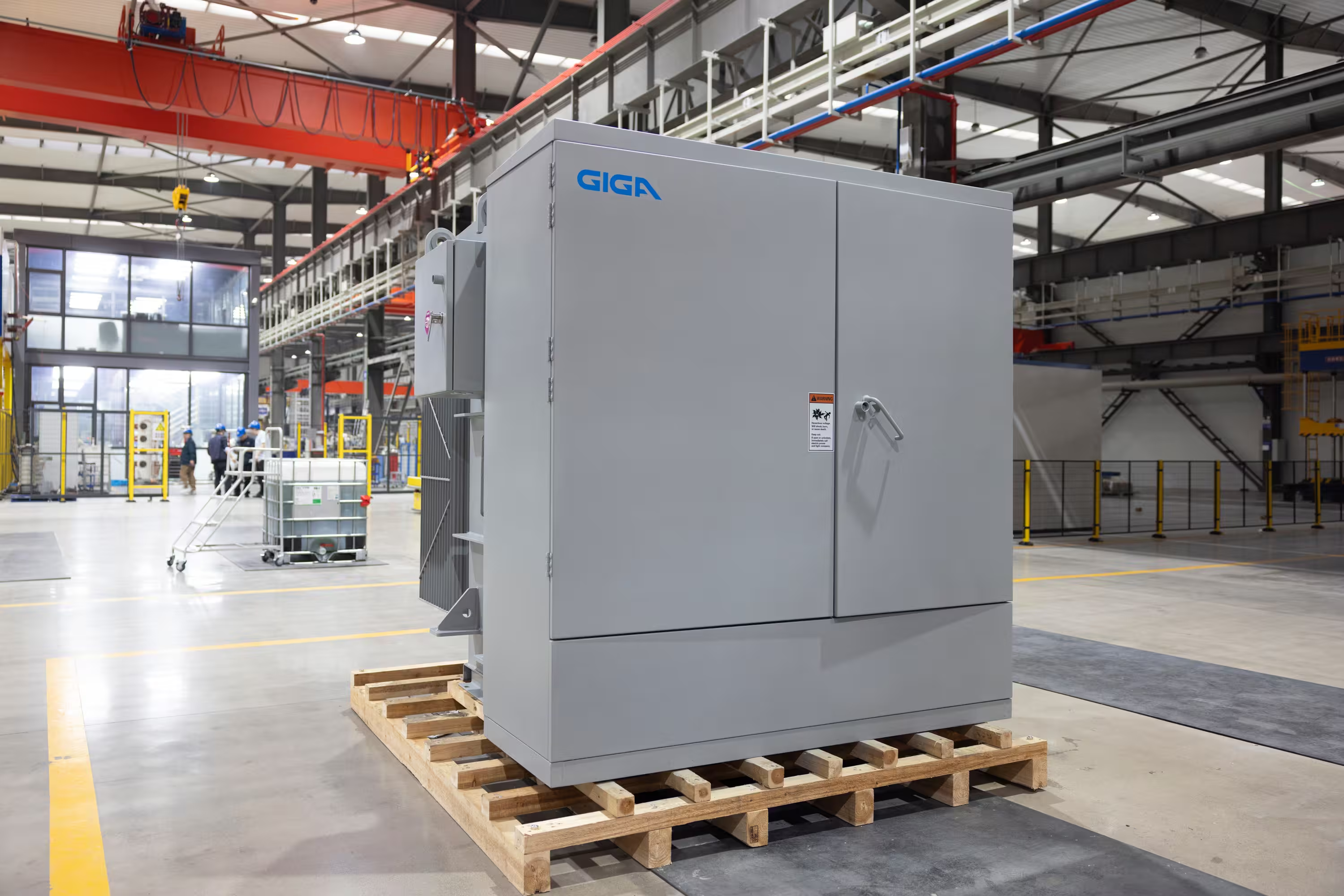
A distribution transformer is a device that steps down the voltage from utility distribution lines to a level your downstream devices can actually use, whether that's manufacturing equipment, HVAC systems, or high-density GPU clusters for AI training. Essentially, your distribution transformer converts grid electricity into usable power for your equipment.
Sizing a distribution transformer is critical. An undersized transformer overheats under load, degrades faster than it should, and risks failure during peak demand periods. A common misconception, then, is to just oversize your transformer to be safe.
Getting your transformer sizing right requires you to understand your load requirements, operating environment, and future plans. That's what we'll walk through here. We will cover the critical parameters that determine which transformer actually fits your application.
Start with your load requirements
All your specs stem from your load calculation. You need to estimate your load requirements accurately to spec equipment that can handle your demand without paying for capacity you don’t need.
Calculate your maximum demand load
NEC Article 220 gives the baseline for load calculations. It's not perfect for every application, but it's the standard reference point you’ll want to start with when beginning your spec.
The formulas depend on whether you're working with single-phase or three-phase power:
- Single-phase: kVA = (load voltage × load current) / (1000 × power factor)
- Three-phase: kVA = (1.732 × load voltage × load current) / (1000 × power factor)
These formulas give you apparent power in kVA, which is what transformers are rated for. Don't confuse this with real power in kW.
Related resource: kW to kVA Calculator
Be sure to account for the difference between continuous and intermittent loads. Continuous loads run for three hours or more and require the transformer to handle sustained heat buildup. Intermittent loads may spike higher, but they don't stress the thermal capacity as much.
Also factor in inrush current from motors, downstream transformers, and other inductive equipment. When motors start or transformers energize, they can draw multiple times their nominal current for brief periods. Your transformer needs enough capacity to handle these surges without nuisance tripping or voltage sags.
Plan for future capacity
Calculating your load capacity is only the beginning. Next, you need to plan for future capacity. The industry standard is to add 25% for future growth. If you don't want to oversize the transformer itself, consider these alternatives:
- Lower temperature-rise specification: Designing a transformer for multiple temperature-rise ratings enables future capacity expansion. For example, a transformer rated at 3,750 kVA with a 55°C rise can be designed to also operate at 4,200 kVA with a 65°C rise, adding 450 kVA of capacity when thermal conditions allow.
- Fan cooling provisions: Forced-air cooling increases transformer capacity when the unit is designed to accommodate the higher load. For transformers under 2,500 kVA, fans add approximately 12% capacity. Units between 2,500 kVA and 10 MVA gain 25%, while transformers 10 MVA and above can achieve 33-67% additional capacity with fan stages (ONAF1/ONAF2). This allows a smaller physical footprint for the same rated capacity.
- Staged deployment: Install transformers in parallel as your load grows. This approach scales capacity incrementally while providing N+1 redundancy for operational reliability.
Consider your power factor
Power factor directly affects how much kVA capacity you need from your transformer. A low power factor means you're drawing more apparent power (kVA) to deliver the same real power (kW) to your load. That inefficiency becomes more evident in larger, more expensive transformers.
Typical power factors by application:
- Industrial loads with motors and inductive equipment: 0.8-0.85, which means you need about 20% more transformer capacity than the real power would suggest.
- Data center cooling equipment with VFDs and compressors: 0.85-0.9, requiring 10-15% additional capacity.
- Bitcoin mining with resistive ASIC loads: Near unity (0.95+), so your kVA and kW are nearly identical.
- AI/GPU compute with modern power supplies: 0.95+ power factor, meaning kVA ≈ kW.
Special considerations for AI data centers
AI infrastructure puts unique demands on distribution transformers that go beyond typical data center loads. GPU clusters for AI training and inference require higher power density, stricter cooling requirements, and built-in redundancy that traditional compute doesn't demand.
- Higher rack density and power requirements: AI racks commonly draw 165 kW or more per rack, which is significantly higher than traditional enterprise IT loads. A single AI compute pod can draw 2.8 MW. This means your transformer needs to handle concentrated loads in smaller footprints, with careful attention to voltage regulation under these dense power draws.
- N+1 redundancy: AI hyperscalers and GPU cloud providers typically require Tier III redundancy (N+1) as a baseline. Plan for parallel transformer operation from day one, with matching impedances and careful load-sharing design.
- Near-unity power factor: GPU loads run at power factors near 0.95 or higher, meaning your kVA and kW requirements align closely. This simplifies transformer sizing compared to industrial or traditional data center applications with lower power factors.
- Speed to deployment: AI compute capacity is constrained by available megawatts, not GPUs. Transformers with quicker lead times can be the difference between capturing market share and losing it to competitors who energize sites faster.
Select primary and secondary voltages
Another critical specification is your primary and secondary voltage.
Your primary voltage is dictated by what the utility delivers to your site, and your secondary voltage is determined by what your facility needs.
Start with your primary voltage by checking with the utility. Distribution voltages vary by region, utility company, and even by feeder within the same service territory. Contact your utility early in the project to confirm the available voltage at your site and any specific requirements they have for transformer connections or protection.
Your secondary voltage depends on your facility's electrical distribution system. Match the transformer secondary to what your switchboards, panels, and branch circuits are designed for. Mismatched voltages mean you can't connect the equipment.
You must also specify your vector group and grounding scheme. Vector group describes how the primary and secondary windings are connected (delta-wye, wye-wye, delta-delta, or less common configurations like wye-delta). Grounding scheme affects fault current behavior, voltage stability during single-phase faults, and safety.
Installing a transformer with the wrong vector group or grounding configuration creates voltage imbalances, neutral current issues, and problems with protective relaying, all of which are expensive to fix after the fact.
Specify construction type and cooling class
Once you know your load requirements, the next decision is what type of transformer fits your installation.
Padmount vs. substation transformers
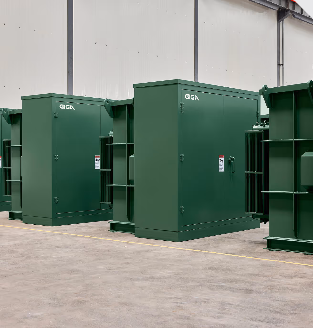
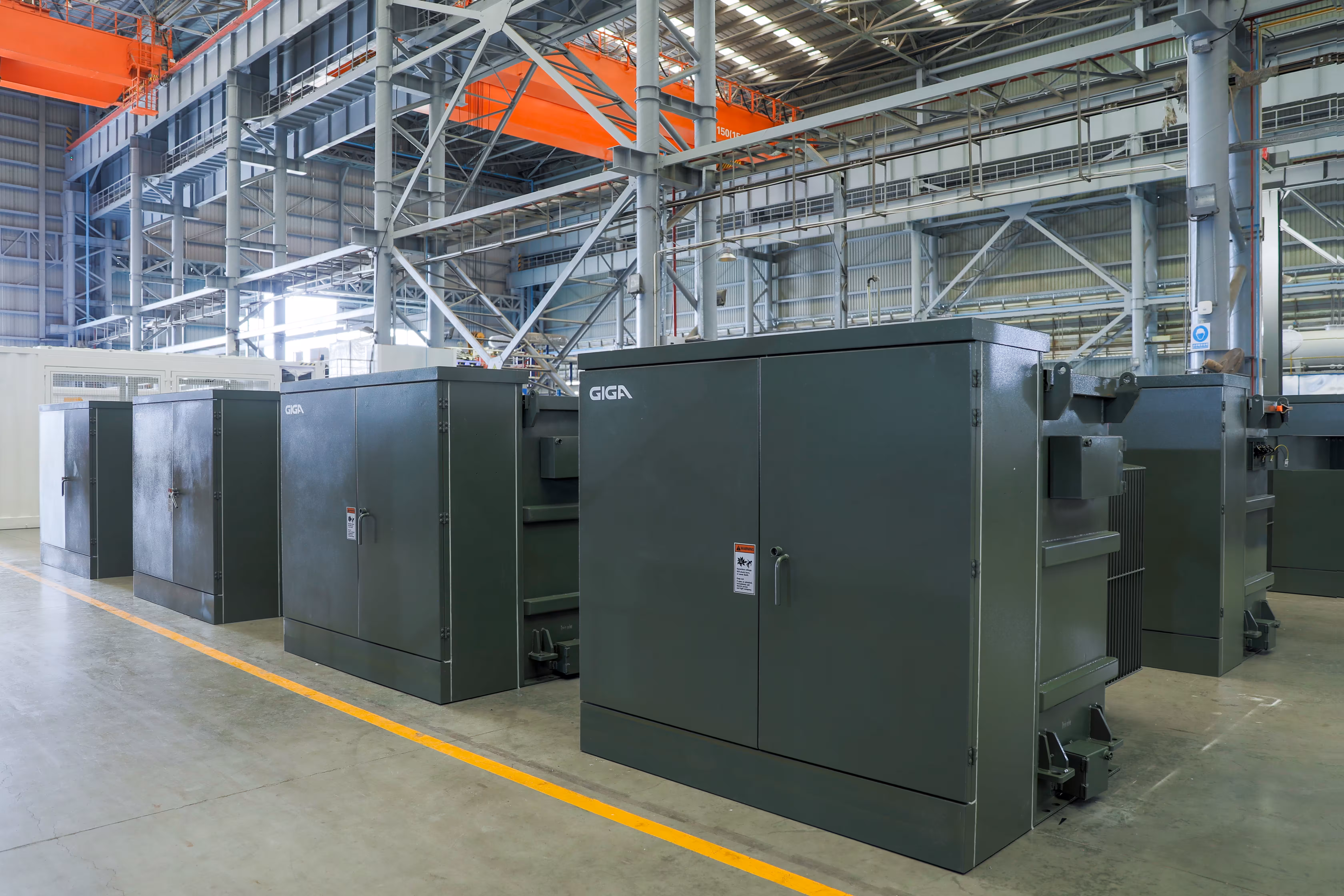
Most commercial and industrial projects use three-phase padmount transformers for medium voltage distribution. They range from 15 kVA to 10,000 kVA and are installed at ground-level on a concrete pad with a lockable, tamper-resistant enclosure.
Substation transformers step up in size and voltage class for larger or more specialized applications. They can range up to 100 MVA, and you'll find them in industrial plants, manufacturing facilities, utility substations, and sites where power requirements exceed what padmounts can deliver.
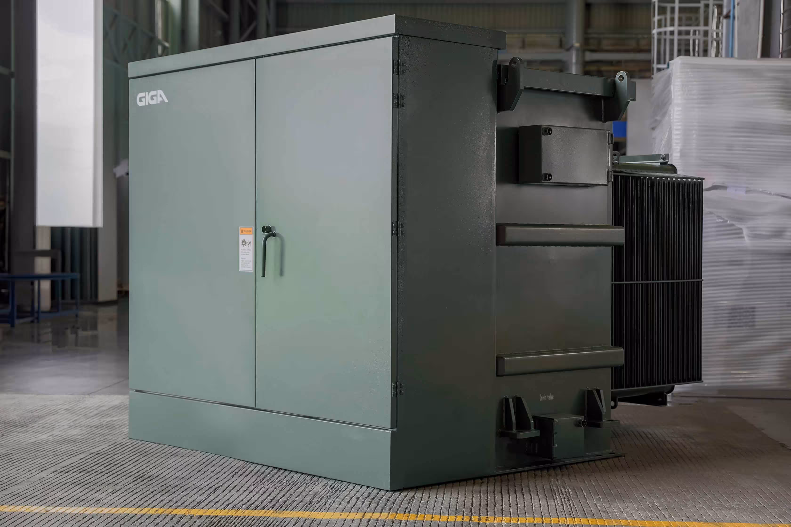
Cooling methods for liquid-filled transformers
Transformer cooling methods are defined by four-letter codes that determine your transformer's capacity and its heat dissipation. The four-letter codes break down like this: internal coolant type, internal circulation, external coolant, external circulation.
- ONAN (Oil Natural, Air Natural): In this passive cooling setup, oil circulates naturally to allow heat to dissipate to ambient air through radiators or the tank’s surface.
- ONAF (Oil Natural, Air Forced): This natural-oil-based cooling class adds fans to blow air across the radiators, increasing heat dissipation by 15-33% depending on transformer size.
- KNAN (K-fluid Natural, Air Natural): Follows the same passive cooling logic as ONAN but uses Cargill FR3 or another high-fire-point natural ester fluid instead of mineral oil, with the "K" indicating the fluid type.
- KNAF (K-fluid Natural, Air Forced): Combines fan-assisted cooling with FR3 or high-fire-point fluid, following the same capacity increases as ONAF.
Unsure of whether you need fans or passive cooling for your build? Fans make sense when you need the extra capacity and can manage the trade-offs. They add noise (typically 10-15 dBA), require electrical connections and controls, and introduce additional maintenance requirements. Fan cooling can be more cost-effective than buying a larger transformer, but for noise-sensitive environments, you may want to go with passive cooling.
Account for operating environment and special requirements
Standard transformer ratings assume ideal conditions, but your site might not have ideal conditions. Temperature extremes, altitude, and seismic risk all change what your transformer can deliver. Let’s explore several key operating conditions that may impact your distribution transformer.
Temperature and altitude considerations
Transformer ratings are based on a 30°C ambient temperature assumption (about 86°F). If your site runs hotter than that, and you need to derate capacity or specify a unit designed for higher ambient temperatures.
The exact derating depends on transformer type and insulation class, but a general rule is 1-1.5% capacity loss per degree over 30°C. A transformer in a 40°C environment (104°F) might lose 10-15% of its rated capacity.
Next, consider your altitude. Transformers installed above 3,300 feet require derating or special design considerations. When you are above this altitude, you begin to lose capacity at a rate of roughly 0.3-0.4% per 330 feet.
Finally, consider ventilation. Heat buildup in an enclosed space will push ambient temperatures well above the standard rating levels. Specify ventilation requirements or consider a dry-type transformer if your facility is too tight to allow for a liquid-cooled unit.
Harmonics and K-factor
Harmonics are distortions in the electrical waveform caused by nonlinear loads. They generate additional heat in the transformer without doing useful work, which means the transformer must be sized larger or specially rated to handle the thermal stress.
Harmonic currents increase losses in the transformer windings and core, particularly eddy current losses in the conductors. A transformer that can safely handle 1,000 kVA of linear load might only handle 800 kVA of nonlinear load with high harmonic content. If you don't account for this, you end up with a hot, overloaded transformer.
K-factor ratings quantify a transformer's ability to handle harmonic loads. K-factor ranges from K-1 (linear loads, no harmonics) to K-20 (severe harmonic distortion) or up to K-50 for certain dry-type transformers. If more than 50% of your load consists of power electronics, you should specify a K-rated transformer.
Additional specifications to consider
Finally, consider some site-specific needs and limitations when specifying your distribution transformer.
- Voltage regulation and tap changers: Utility voltage varies with grid load and distance from the substation. A transformer with an off-load tap changer lets you adjust the turns ratio to compensate for high or low input voltage, keeping your output voltage within an acceptable range.
- BIL (Basic Impulse Insulation Level): This is the transformer's ability to withstand voltage surges from lightning strikes or switching events. BIL is rated in kilovolts and varies by voltage class. Higher BIL is more expensive, but offers better surge protection.
- Sound levels: Transformers hum. The question is whether that hum is acceptable for your site. For installations near occupied buildings, schools, hospitals, or residential areas, specify sound-level limits in your transformer specification.
- Seismic certification: Seismic-rated transformers are designed and tested to withstand earthquakes without structural failure or loss of function. This involves anchoring, bracing, and, in some cases, specialized mounting systems.
- Redundancy and parallel operation: Parallel operation requires careful engineering, as transformers must have matching impedances, voltage ratios, and phase angles; otherwise, they'll circulate current and create losses or instability. If redundancy matters to your operation, work with your engineering team to design it correctly from the start.
Choose accessories and monitoring provisions
Your distribution transformer is just one part of your system. To operate safely and efficiently, you also need the right accessories and monitoring equipment.
Primary side protection
The primary side (where the utility voltage enters the transformer) requires protection against faults, surges, and overcurrent conditions. Let’s examine the accessories and fusing options you can use to protect your transformer.
- Fused cutouts vs. circuit breakers: Fused cutouts are the standard for padmount transformers. Circuit breakers offer more control and can be reclosed remotely, but they're more expensive and typically reserved for larger substation applications.
- Surge arresters for lightning protection: Surge arresters clamp voltage spikes and divert energy to ground before it reaches the transformer. Specify arresters for all outdoor installations, especially in areas with frequent lightning activity.
- Load break vs. dead break bushings: Load break bushings allow you to disconnect the transformer under load using a hot stick. Dead break bushings require the system to be de-energized before disconnection.
- Loop feed configurations for redundancy: Loop feed means multiple sets of primary bushings per phase, allowing the transformer to tie into a utility loop or provide feed-through to downstream equipment.
Secondary side components
The secondary side (where voltage exits the transformer to your facility) also requires metering and monitoring. Let’s explore some common considerations here.
- Integrated vs. separate switchboard: Some projects integrate the switchboard directly with the transformer as a single unit. Separate switchboards cost more upfront and take up more floor space, but are easier to service.
- Metering and monitoring requirements: Some monitoring accessories you might want to explore for your distribution transformer spec include the following.
- Current transformers (CTs): Measure load current on each phase. These are required for metering, monitoring, and protective relaying.
- Voltage transformers (VTs or PTs): Measure voltage on the secondary side. These are less common than CTs and are used for power metering and voltage monitoring.
- Temperature monitoring: Track winding hot-spot and oil temperature, as these are early warning indicators for overload or cooling system problems. Specify gauges with alarm contacts that integrate with your facility monitoring system.
- Power quality metering: Advanced metering captures harmonics, power factor, voltage sag/swell, and other parameters. Useful for data centers, facilities with sensitive equipment, or sites where you need to diagnose power quality issues.
If your facility uses SCADA or a building management system (BMS), your transformer monitoring equipment needs to communicate with it. This typically means specifying alarm contacts, communication protocols, and ensuring compatibility between the transformer instrumentation and your control system.
Safety and serviceability features
Transformers need to be safe to work on and easy to maintain. The following features are critical for technicians to service your equipment without unnecessary risk or downtime.
- Lockout/tagout provisions: LOTO points allow you to physically lock the transformer in a de-energized state during maintenance. Ensure that your distribution transformer has accessible, clearly marked LOTO points on both primary and secondary disconnects.
- Pressure relief devices: Liquid-filled transformers generate gas when internal faults or overheating occur. Pressure relief valves vent this pressure to prevent tank rupture. They're standard on most transformers, but verify they're included and properly rated for the transformer size and fluid type.
- Liquid level and temperature gauges with alarm contacts: Visual gauges and alarms allow you to check fluid levels and temperatures and alert you if temps go beyond safe thresholds.
- Drain and sample valves: These allow you to drain fluid for maintenance or take samples for oil quality testing. Specify external, lockable drain valves on all liquid-filled transformers to make long-term maintenance simpler.
- Ground pads and neutral connections: Proper grounding is critical for safety and system performance. The transformer tank, neutral point, and ground connections must be accessible, clearly marked, and sized correctly for fault current.
Common distribution transformer sizing mistakes to avoid
Most transformer failures are caused by issues that start during specification. If you get your specs wrong, you’ll end up with equipment that doesn’t fit your application and is, ultimately, far more likely to fail.
Mistake #1: Ignoring power factor in calculations
One common mistake is specifying a transformer based on kW alone. If you make this mistake, you’re ignoring the power factor and undersizing your unit.
Let’s walk through the math. If you have a 1,000 kW load with a 0.8 power factor, your actual demand is 1,250 kVA. When you spec a 1,000 kVA transformer, you're actually 20% under capacity.
If you neglect to consider power factor when specifying your distribution transformer, you will end up running your transformer at 110-120% of rating during normal operation, setting yourself up for a shortened service life at best and catastrophic failure at worst.
Mistake #2: Not planning for future growth
A transformer replacement is expensive and disruptive. You’ll need to invest in new equipment, pay to remove and dispose of the old unit, plus account for site work and downtime during installation. Overall, you may think you’re saving money by sizing your transformer to your exact day-one load, but when you don’t account for growth, you’ll end up paying way more in the span of 18-24 months.
That being said, you don’t want to massively oversize your transformer, either. How do you strike the right balance?
Oversizing is smart when growth is certain and the timeline is clear. It doesn't make sense for speculative growth with no timeline or budget, or when you're better served by staged deployment of parallel units. This staged approach is especially common in AI data center builds, where hyperscalers deploy GPU capacity in phases as power becomes available.
Pro tip: If your load might double in five years, consider two smaller transformers instead of one oversized unit. You get redundancy, better efficiency at partial loads, and flexibility to match capacity to actual growth.
Mistake #3: Overlooking site-specific requirements
Standard transformer specs work for standard sites. Your site probably has at least one non-standard requirement that will cause problems if you don't address it upfront.
- Fire codes: Urban installations, underground vaults, hospitals, schools, and buildings with occupied spaces often require dry-type transformers or less-flammable insulating fluids. If you need FR3 or other high-fire-point fluids, you need to specify them upfront, as they're not changes you can make late in the project without additional cost and lead time.
- Utility-specific standards and approvals: Some utilities have approved equipment lists or require specific transformer configurations, protection schemes, or metering provisions. If your transformer doesn't meet utility requirements, they won't energize it, so check these standards before finalizing your specs.
- Seismic or environmental factors: California and other seismic zones require certified transformers with proper anchoring and bracing. Coastal or high-humidity environments may need upgraded corrosion protection. Sites with flood risk might need submersible-rated enclosures. Consider all environmental factors that apply to your site and address them during the specification process.
Mistake #4: Choosing based solely on price
Transformers are capital equipment with service lives of 20-30 years. Buying the cheapest option without evaluating quality, efficiency, and support will ultimately cost far more over time.
Low-cost transformers often use lower-grade core steel, thinner tank walls, cheaper bushings, and minimal quality control. They meet basic ratings on paper but fail earlier, run less efficiently, and cause more problems.
You also need to consider the quality of engineering support offered by your manufacturer. Vendors who disappear after the sale or require weeks to answer basic questions cost you time and money. Evaluate support capability as part of the buying decision.
How to spec the right distribution transformer with Giga
Getting your distribution transformer specs right comes down to five important engineering decisions:
- Your load requirements now and in the future
- The voltage levels that match your utility supply and facility distribution
- The construction type and cooling method that fit your site
- The operating environment and special requirements your application demands
- The accessories and monitoring you need to operate safely
Working with Giga simplifies the process because you're talking directly to the engineers who design and build the transformers. Instead of back-and-forth through multiple departments, you get engineer-to-engineer consultation from people who understand the application and can answer your most technical questions.
Our vertical integration means we control the entire process. We're not brokers sourcing from factories we don't manage. We engineer the transformers in-house, oversee production, and deliver on the lead times we commit to.
Here's how the process works when you spec a transformer with Giga:
- Technical consultation to understand your application, load profile, site conditions, and any special requirements
- Accurate engineering and proposal with detailed specs, drawings, and transparent pricing
- Drawing approval before manufacturing, so you verify the design meets your needs before we build
- Factory acceptance testing to ensure the transformer performs to spec before it ships
- Delivery and ongoing support with our engineering team available for commissioning, troubleshooting, and service
Ready to spec your transformer? Build a quote or contact our sales team for more information today.