Even experienced distributors and others in the electrical industry don’t always know the difference between KNAN/KNAF and ONAN/ONAF cooling classes. What do those ratings mean in practical terms, and why don’t we always spec transformers with the highest-rated cooling stage by default?
As it turns out, there’s a lot of nuance packed into those four-letter acronyms. Even among seasoned engineers, confusion persists regarding how these classes are defined in IEEE standards, how much capacity they really add, and what trade-offs they represent in transformer design and deployment.
Read more: Which factors affect lead times for electrical transformers?
In this article, we will unravel the mystery, using IEEE C57.12.00 and C57.12.10 as primary references and providing real-world guidance for distributors, electrical engineers, procurement leads, and technical teams making transformer decisions.
.avif)
What are transformer cooling classes?
Transformer cooling classes are defined by a standardized four-letter code that indicates both the type of insulating fluid used and the cooling mechanism employed. These codes follow a specific structure laid out in IEEE C57.12.00, Annex A.
- First Letter: Internal coolant (O = Oil, A = Air, K = Ester fluid)
- Second Letter: Internal circulation (N = Natural, F = Forced, D = Directed)
- Third Letter: External coolant (A = Air, W = Water)
- Fourth Letter: External circulation (N = Natural, F = Forced)
The first letter refers to the type of fluid inside the transformer. “O” indicates mineral oil, which is the traditional and still most commonly used dielectric fluid that fire point is ≤ 300 °C. “K” refers to high fire point insulating liquids, typically natural esters like FR3, that meet a fire point threshold of ≥300°C.
The second letter indicates how heat is moved through the internal fluid: “N” stands for natural circulation, and “F” would indicate forced fluid flow if it were used.
The third and fourth letters describe how heat is dissipated into the environment, either naturally (“AN” for air natural) or with forced air (as in “AF” for air forced, usually via external fans).
Put together, ONAN describes a mineral-oil-filled transformer using passive (natural) circulation inside and relying on ambient air to dissipate heat. KNAN means the same setup, but with a high fire point fluid instead of mineral oil. ONAF and KNAF build on these foundations by adding fans to increase the air flow across the radiator surfaces, improving heat rejection and allowing for higher transformer loading.
Read more: How do transformers work?
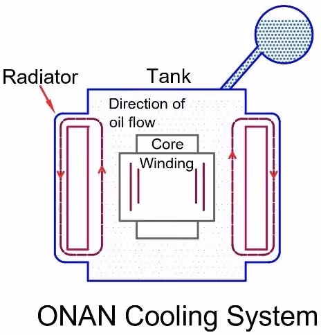
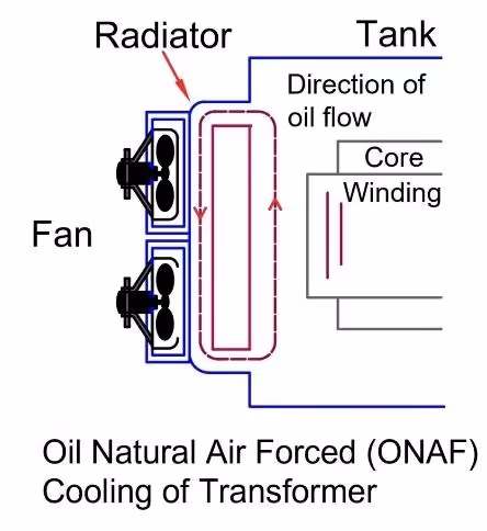
ONAN vs ONAF: Understanding mineral oil cooling stages
ONAN and ONAF are the most common cooling classes seen in distribution and power transformers using mineral oil. ONAN represents the base rating: this is the passive, unassisted state in which the transformer operates under natural convection. Heat generated in the windings is carried by the oil up to the radiators, where it is transferred to the surrounding air.
When the load increases and internal temperatures rise, fans kick in to create the ONAF state. This is a forced-air cooling mode that significantly enhances heat dissipation, allowing the transformer to safely carry more load. In IEEE C57.12.10, transformer ratings are clearly specified to increase at defined increments depending on the transformer’s base size. For example, transformers rated below 2500 kVA (three-phase) or 833 kVA (single-phase) typically receive a 15% boost in capacity when forced air cooling is applied. Medium-range transformers from 2500 to 10,000 kVA may be rated for a 25% increase under ONAF, while units above 10,000 kVA can see a 33% increase in ONAF1 and up to 67% under a second fan stage, known as ONAF2.
This stepped cooling model allows transformer designers to offer flexible performance envelopes without overbuilding the core and winding systems. It also allows operators to defer fan operation until required by higher loads, improving energy efficiency and reducing wear on auxiliary systems.
KNAN vs KNAF: How high fire point fluids affect cooling
KNAN and KNAF follow the same cooling logic as ONAN and ONAF, but with one key difference: the fluid inside the tank. K-class fluids like FR3 or other natural esters have a higher fire point than mineral oil, often exceeding 300°C. This makes them attractive for installations in urban areas, substation vaults, hospitals, schools, or anywhere that fire risk mitigation is a design priority.
While K fluids are safer and biodegradable, they also behave slightly differently thermally. Their viscosity, heat transfer rates, and aging characteristics vary from those of mineral oil, and all these factors influence cooling performance. That’s why KNAN is not always a drop-in thermal replacement for ONAN: it may require different radiator sizing or fluid volume or insulation design to match performance. The same applies for KNAF compared to ONAF.
In many cases, the thermal performance of KNAN and KNAF is engineered to match their “O” counterparts, but it must be validated per IEEE thermal design procedures. This is especially important when upgrading or specifying transformers for existing systems that were originally mineral oil-based.
The difference between natural easter, Synthetic easter, and mineral oil is as below:
The true capacity impact of cooling stages is not always linear
One common misconception about fan-assisted transformer cooling is that the extra capacity scales uniformly across all units. In reality, IEEE defines different kVA multipliers for forced cooling depending on the transformer’s base rating.
According to C57.12.10, transformers under 2500 kVA typically get a 15% capacity bump when fans are enabled. Units between 2,500 and 10,000 kVA see a 25% increase. Large power transformers above 10,000 kVA often get a 33% increase with a first stage of fan cooling (ONAF1) and an additional bump up to 67% total capacity at a second stage (ONAF2).
These multipliers are based on thermal modeling and empirical testing, and they assume standard service conditions such as 30°C ambient air temperature and correct installation of fan banks. They do not apply linearly across all unit sizes, and they cannot be assumed in every application without checking the nameplate ratings and thermal design documentation.
This is where misunderstandings often arise. A 5,000 kVA transformer may safely carry 6,250 kVA under ONAF, while a 15,000 kVA unit might reach 25,000 kVA under ONAF2. But these are not blanket assumptions: they are engineering limits validated through test and design models, not simple percentages.
Read more: Different types of transformer connections and how they work
Why are transformers not built to ONAF2 by default?
If higher capacity is possible with enhanced cooling, why not design all transformers to operate at ONAF2 right out of the gate? The answer lies in trade-offs, specifically in cost, complexity, physical size, and operational requirements.
Designing a transformer to support ONAF2 means more than just bolting on additional fans. It typically requires a larger radiator bank, increased fluid volume, more powerful fan motors, and potentially heavier-duty structural supports. Internally, the windings may need to be sized differently to handle higher thermal stress, and the insulation system must be rated for the elevated temperatures associated with sustained high loading.
These changes increase both capital costs and lead time. For customers that will never push their transformers beyond ONAN or a first stage of fan cooling, those extra features are unnecessary and uneconomical. In other cases, application-specific needs such as space constraints, noise limits, or SCADA control limitations may discourage the use of multi-stage fan banks.
From a procurement standpoint, a transformer designed for ONAF2 operation may also require enhanced monitoring systems. These include temperature sensors, fan controls, and alarms that can coordinate fan operation in response to load conditions. If these systems fail or are not maintained, the additional capacity offered by ONAF2 cannot be safely used. Therefore, engineering teams often opt for conservative designs aligned to expected operational loads, rather than building in headroom that may never be needed.
When to specify ONAN vs KNAN transformers
The choice between ONAN and KNAN is more than a thermal decision. This choice reflects fire safety, regulatory compliance, and environmental considerations. The “K” in KNAN and KNAF signifies a fluid with a flash point above 300°C, usually natural esters such as FR3. These fluids are less flammable than mineral oil and often biodegradable, making them suitable for use in locations with fire containment requirements or ecological sensitivity.
ONAN transformers, which use mineral oil, are generally more cost-effective and slightly more efficient in heat transfer. They are commonly specified in industrial settings, outdoor substations, and other environments where fire risk is managed through other means.
KNAN units are more common in installations where fire safety codes mandate the use of less flammable fluids. These include underground vaults, high-rise buildings, urban infrastructure, and facilities with public access. They are also increasingly chosen by utilities pursuing ESG goals or looking to reduce liability from oil leaks.
It’s important to note that specifying a KNAN transformer involves more than substituting the fluid. Radiator sizes, pumping characteristics, and thermal models may need to be adjusted to accommodate the different physical properties of K-class fluids. That’s why specifiers should always confirm that the cooling performance is properly engineered and validated for the chosen fluid, rather than assuming performance parity with ONAN.
Read more: The buyer’s guide to selection, maintenance, and installation of transformers
Common misconceptions about cooling classes
There are a few persistent myths about transformer cooling methods that deserve correction.
First is the idea that KNAN is simply a fire-safe version of ONAN. While this is partly true from a naming standpoint, it overlooks the thermal performance differences between mineral oil and natural esters. KNAN systems require deliberate engineering to match ONAN performance, and they are not always thermally equivalent on a one-to-one basis.
Second is the belief that adding fans automatically doubles or triples capacity. As we’ve discussed, IEEE defines specific capacity multipliers based on the transformer’s base kVA, and these vary by unit size. For instance, a second fan stage (ONAF2 or KNAF2) may provide up to 67% more capacity, but only if the transformer was designed to support it. Not all transformers are physically or electrically configured to operate at their highest possible cooling stage, and attempting to do so without validation could shorten lifespan or cause failure.
Finally, there’s confusion around what cooling stage is active at any given time. Unless actively monitored and controlled, a transformer may only ever operate in ONAN or KNAN mode. Fan failure, incorrect wiring, or control logic errors can prevent ONAF or KNAF cooling from engaging, leaving capacity unused and risk elevated. This is why correct installation, commissioning, and SCADA integration are essential when multi-stage cooling is part of the design.
Practical guidance for engineers and procurement teams
Whether you’re specifying a new transformer or evaluating options from a vendor, it’s critical to understand what the nameplate is telling you. Cooling class ratings should be listed in order—for example, “ONAN/ONAF” or “KNAN/KNAF.” These define both the base rating and the maximum rating with forced cooling.
Ask for manufacturer test reports or IEEE-compliant design documentation to verify what capacity increase is available at each cooling stage. Confirm whether the unit is wired and commissioned for fan operation, and whether fan controls are automated or manual.
Also consider the operational context. Will the transformer serve variable loads that would benefit from fan-assisted headroom? Will ambient temperatures regularly exceed standard assumptions? Will you have the ability to monitor winding hot spots and top oil temperatures in real time? These questions help define whether multi-stage cooling is worth the added complexity.
Procurement teams should also factor in long-term serviceability. KNAN and KNAF transformers may require specialized fluids or filtration systems. ONAF2 systems may require periodic fan maintenance or component replacement. Budgeting for these life-cycle costs upfront can prevent surprises later.
Summary of transformer kVA increases
This is a simplified reference to understand how cooling stages increase transformer capacity depending on size:
- For transformers rated under 2,500 kVA 3-phase, first stage forced air (ONAF1 or KNAF1) increases capacity by 15%.
- For transformers rated between 2,500 and 10,000 kVA, the capacity increase is 25%.
- For transformers rated above 10,000 kVA, the first stage provides a 33% increase, while the second stage (ONAF2/KNAF2) allows up to 67%more than the base rating.
Note that these are standardized reference points. Actual performance depends on engineering design, fan installation, control system functionality, and environmental conditions.
Making smarter decisions about transformer cooling methods
Understanding transformer cooling classes is more than decoding acronyms. It’s about aligning thermal performance, safety requirements, and application context. ONAN and KNAN serve as the base thermal states for mineral oil and high fire point fluids, respectively. ONAF and KNAF introduce fan-assisted cooling that can unlock significant capacity, but only when engineered, installed, and maintained correctly.
Cooling stages aren’t linear, and they aren’t uniform across transformer sizes. IEEE standards provide clear guidance, but it’s up to specifiers and engineers to interpret those rules in real-world scenarios. Whether you’re designing a substation, upgrading utility infrastructure, or managing a critical facility, understanding how transformer cooling works, and when it matters, can save cost, reduce risk, and improve reliability.
If you’re unsure which cooling configuration is right for your project, Giga’s technical team can help you evaluate trade-offs and design constraints. Reach out to schedule a consultation and ensure your next transformer is built to handle both the load and the heat.